
/* Name : main.c
* Purpose : Source code for UART Interfacing with AT89C52.
* Author : Gemicates
* Date : 2017-06-21
* Website : www.gemicates.org
* Revision : none
*/
#include <regx52.h>
#include <string.h>
#define lcd P2
sbit rs=P1^0;
sbit rw=P1^1;
sbit e=P1^2;
// LCD FUNCTIONS
void lcddata(char t);
void lcdstring( char *l);
void cmd(unsigned char);
void com();
// UART FUNCTIONS
void init();
void tdata(unsigned char);
unsigned char rdata(void);
//DELAY FUNCTION
void delay(unsigned char);
//MAIN FUNCTION//
void main()
{
unsigned int i,j;
unsigned char c,*d;
d="gemicates"; // Tranamitted Value
j=strlen(d);
P1=0x00;
P2=0x00;
init(); // UART intialization
com(); // LCD intialization
cmd(0x80);
lcdstring("TRANSMITTED CHAR"); // LCD string Print
// CHARCTER TRANSMISSION LOOP
cmd(0xc4);
for(i=0;i<j;i++)
{
tdata(d[i]);
lcddata(d[i]);
}
delay(1000);
cmd(0x01);
cmd(0x82);
lcdstring("RECEIVED CHAR"); // LCD string Print
cmd(0xc7);
// CHARCTER RECEIVE LOOP
while(1)
{
c=rdata();
lcddata(c);
cmd(0xc7);
}
}
//SUB FUNCTIONS//
void delay(unsigned char t) // Delay Function
{
unsigned int i,j;
for(i=0;i<t;i++)
for(j=0;j<1275;j++);
}
void init() // UART INITIALIZATION
{
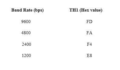
TMOD=0x20;
TH1=0xFD;
SCON=0x50;
TR1=1;
}
void tdata(unsigned char t) // DATA Transmission
{
SBUF=t;
while(TI==0);
TI=0;
}
unsigned char rdata(void) // DATA Receive
{
unsigned char d;
d=SBUF;
while(RI==0);
RI=0;
return d;
}
void lcddata(char t) // LCD Data Function
{
rs=1;
lcd=t;
rw=0;
e=1;
delay(1);
e=0;
}
void cmd(unsigned char c) // LCD Command Function
{
lcd=c;
rs=0;
rw=0;
e=1;
delay(1);
e=0;
}
void com() // LCD Decleration Function
{
cmd(0x38);
delay(10);
cmd(0x0c);
delay(10);
cmd(0x01);
delay(10);
cmd(0x80);
delay(10);
}
void lcdstring(char *l) // LCD String Function
{
while(*l !=0)
{
lcddata(*l++);
}
}

Interfacing of UART with 8051